P1 Vacumm cleaner
The first challenge of this subject is to implement the vacumm cleaner we did last year but this time with autolocalization. To implement this we are going to use the BSA Algorithm.
This is a coverage algorithm which consists in using a mesh to cover all the space. Apparently its really simple, it could be split in 4 steps:
1. Create the map mesh. It will help us to know where the objects are, which are the positions that the robot has visited...
2. The robot movement. All the position visited are marked in the mesh, also we save the positions visited which have unvisited neigbours (this will be our return points). The robot will move in one direction until it finds any object or position visited in front of him.
3. When the robot is stuck becouse he finds an object or visited cell and there is no other free cell around it, we will have to find the nearest return point to our robot and calculate how to reach that point.
4. Once we reach the return point we will be back to the second step.
Now that is explained the method to resolve the problem let's start coding!
1. Create Mesh
So as i said before, in order to make the autolocalization we create a mesh to indicate where are the robot, the obstacles and the positions we have had visited.
First of all after we get the image we should erode it. This is to make bigger the obstacles and avoid the robot collides with them. Here is a comparation of both images:
 |
| Original map |
 |
| Erode map |
The erosion can be more appreciated at the table legs of the living room, they are wider in the eroded map.
Now that we have the real map we are going to work with, its time to start with the grid. Our map has 1008x1007 dimensions, this is too big, so i resize the map to a value of 575x575.
On the other hand, i decided that each of the grid cells it's equal to a matrix of 17x17 pixels (becouse i think it's the value more close to what the robot occupies).
Once we know this i create the mesh and start iterate over the map pixels with an increment of 17 pixels (which is the equivalent to one of the mesh squares). And i look if between thouse 17x17 pixels is any of them black, becouse if there's one black that square of the mesh is going to be black. Let's get a deeper look of this:
We start to iterate in the pixel (0,0), then i create a submatrix with the pixels from the position 0 to 17 in width an 0 to 17 in height. Then i look if any of thouse pixels are black, if there is at least one, the mesh in that position would be colored in red otherwise i don't change the color. In the next iteration, as i iterate with an increment of 17 the next value for i,j is going to be 17 and i create again a submatrix, this time with the values of the image from position 17 to 34 in width and height, and look for the black pixel. The next iteration i,j will have a value of 34, and submatrix will be from 34 to 51, and this sucesively...
But while i was trying my code i noticed a small error in the given map that was making my robot behave wrongly. The problem is the next, when the robot is in the upper bedroom there is a selvebook which was't well represented in the map, so when the robot is next to it:

The map was telling that next to it, there was already free space, as you can see in the next image:

So for the robot there was a free cell that has to be clean, but it ended up crashing with the selvebook, so never reached and cleaned:

Therefore i had to modify the map so the bookselve is well positioned. The new map is the next:

As you can notice theres hardly any change in the map, but the little modification on the selvebook will allow my robot had a correct behaviour.
The grid built with this map eroded is:

Every cell which has any black pixel will be transform into a red cell, as you can see in the next image which is the final grid created by Unibotics:

2. Robot movement
To address this problem i'm going to focus for now on the robots brain. So to make this easier i would suppouse that i know the transformation between the 3D world and the 2D mesh (in other worlds, i'm going to work with the mesh positions). Let's make clear that this process was made directly on my computer, outside the Unibotics platform and once i get this and the transform matrix i will unify all together on Unibotics.
Logic of the movement
Get next position
Let's start defining the directions preferences, where is going to move the robot? When he could go anywhere (there is no objects next to him) what will it prefer? Move up, go right...?
What i made is to define an array with the vectors of the posible directions from the map point of view (North, South, West or East) which is going to be something like [(-1,0),(1,0),(0,-1),(0,1)]. The vector which is in the first position is the highest priority direction and the last position the least priority. So in every iteration the robot will check if he can go in the first direction, if not he would check the others until one of them is free. We can see this behaviour in the next video:
As we can see once we reach the upper left corner of the room it gets stucks becouse there is no more free cells. Lets solve this problem!
Return points
First of all we should know which are the positions the robot can go back. This are going to be the cells which has free neighbors, so in each iteration the robot has to check if the position that is in has any adjacent free position. If it has, he would add the actual position to a list (which will contain all the return points).
Also we will have to check if the positions that are already in the list still valid or theirs neighbors now are visited.
For do this, i have a loop which will check the neighbors positions of the actual position (the cell which is one position above, below, righ or left) and add it to the list if has any adjacent cell free. But also inside this loop i check if any of the neigbors is already in the list, and if it should keep in the array or should left becouse there is no free adjacent position to it. So inside the loop i also have another loop to look for the neightbors neighbor.
I leave you a picture here that i made to explain the loop more visualy:

So in the first loop i will check the magenta neighbords of the actual position and for each of those positions i check if they where in the list. In this case the neighbord 1 and 2 where in the list, so there is another loop that check their respective neightbords (the pink cells). If one of it's respective pinks cells is empty that neighbord can stay in the list.
Path resolver
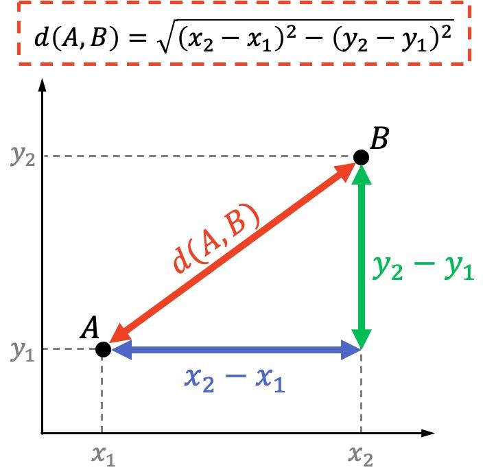
Now that we have our return point list it's time to see which of thouse points are nearest to the robot position. For this i use the formula to know the distance between two points and select the point which give the minor distance.
I also make a check to know if between thouse points is any occupied cell and have that in mind to make the robot look for other more clear path. The way i make this is getting the submatrix of all the cells between the robot position and the posible return point. With this sybmatrix i count the number of times there is a red cell, this number is added to the distance (in order to make the distance bigger). So the robot will select the cell not only more close but also the one with less obstacles between them.
Okey, we have now the closest point but, How the robot would reach it? Well to solve this problem i used the Breadth First Search (BDF).
I use this method becouse i think is one of the most simple and easy to get the path we are looking for. Here i leave you quick explanation of how it works:
You will start looking from the goal position and visit the neighbords until one of that neighbords is the actual position of the robot. The behaviour is like we can see in the image below.
 |
| Gif from this page. |
The objective of this algorithm in our case, is to explore all the neighbords cells before take one more step. With this we will obtain the the best and shortest path to reach the goal positon.

First of all you will have to create an empty array which will contain all the possible path that is exploring the algorithm.
So in the first iteration of the algorithm, it will create an array with each neighbord that is a non visited cell. For example you could obtain from the first iteration an array of four arrays ([[goal_pos, neighbord_north],[goal_pos, neighbord_west], [goal_pos, neighbord_south], [goal_pos, neighbord_east]]). And with each iterarion each of the arrays will increase with new non visited neightbords cells and not occupied cells, also more posible path arrays will be addded until the robot position is found.
Once the position of the robot has been discovered, the array with the path is return. This array begins with the goal position and ends with the actual position of the robot so all you will have to do is to iterate over this array backwards and you will get all the steps the robot has to do to reach the objective.
Okey we did a lot of things. At this point i have this execution:
As you can see in the video, when the robot is sourronded by blue cells and the slected return position is close to the actual position, it takes very short time to found the path. But when there is only two groups of cells left to clean the path is more complicated and it takes too long to resolve it. So i have to solution this.
Middle points
Which is my solution?
Well i define an array with middle points. This " middle points" are key position of each room, for example i define this:

So when the robot gets stuck becouse it can't find a path (this mean it has exceed a number of iterations) what i made is to find the nearest middle point to the destination cell. Now that middle point is going to be the temporal destination cell. And from this new objetive point i look if there is a way for the robot to reach it (less than the number of iterations). If there is a way, perfect!, the robot would go first to the middle point and from that point it could find a way to reach the real point. The way to find the path is the same, with the BDF method.
If from that new point it can find a path it would look for other middle point, the nearest to the actual and from that point will look for a way to reach it. The other middle point which was visited and didn't help to find a path would be mark has visited so the robot wouldn't take it again as a posible middle point to reach the objective.
Once that achives the middle objective point, it would again look for the nearest visited cell with free neighbords. And the process will start once more if he can't reach directly it would find a path, if not he would try by the middle points.
Here is a demostration:
I hope the next image explain this a little bit.

The next objective cell will be the dark magenta (2º iteration color), it cannot get a path so the closest point is the magenta, the 3º iteration color (the dark red wouldn't be selected becouse we have already see it). And it will continue until from the middle point select can calculate a path.
For last i added a little modification, every time the robot reach a middle point it looks again to the posible return point to see if there is anyone closer. With this it could work more efficiently. About the code i had to add only an if condition that check the return points.
So with this we have completed all the logic of the robot, now its time to code this in the 3D world.
Implementation in the 3D world

x = -a x' + b
y = c y' + d

- Turn function
So in order to be able of turning to the correct side each time,
i use a series of ifs. But first, lets explain all the orientations that the robot can reach.

- When the robot is at -1.57 and want 3.14 orientation:
With the two conditions explained before the robot will start to turn to the left, but is more quick to turn to the right to reach that orientation. So i add a condition in which if the robot is in -1.57 and wants to go to 3.14 the angular velocity should be positive.
- When the robot is at 3.14 and wants to go -1.57:
Basically is the same condition of the previous case but with the orientation changed. So i did the same, if the robot is in 3.14 and the next orientation is -1.57 command a negative velocity. Be aware that this case should be before the first one mentioned (when the robot orientation is bigger than the next position, otherwise it will keep turning right).
- When the robot has a close orientation to 3.14 but HAL.Pose3d().yaw return a negative orientation:
As i warn you before, when the robot orients to the East it could return a negative or positive number. To solution this i use the fuction i mention before (the one which returns the "ideal" orientaion that is more close to my actual orientation, so in case the HAL returns an orientation of -3.1 i pass as an argument the absolute, 3.1). So when the next orientation an the acual "ideal" orientation is the same and the orientation ruturned by HAL is less than 0 it shoul rotate to the right.
For this case the optimum rotation is going to be to the right side. In this case we can't apply the rule that if the robot orientation is bigger than the next orientation, turn to the right, becouse we have a negative orientation for example -2.98 that is close to 3.14. So it's necessary a last case in which when the exact orientation is 3.14 and the next orientation is 1.57 turn to the right, with this we avoid problems on the turning side with the positive or negative orientations close to 3.14.
I know this is a little bit tricky but if you use the previous image to reason the direction of rotation is more easy.
Now to reach the goal orientation i have only to use a while loop which is continuosly looking if the diference between the actual orientation and the goal has an error smaller than 0.03.
In the case that the next orientation is more or less the robot orientation i command a smaller angular velocity in order to make a more exactly turn.
- Next position function
This function will allow us to make the robot reach the next position given by the robot logic.
Once we are correctly orientated we have only to command the robot a linear velocity until it reach the next cell. So this function has to know which is the next desired position.
The robot logic will give us the next cell position, but this is not exactly the robot ojective. In a mesh world it would be enough but in the "real world" of Gazebo we don't want to reach exactly, for example the (5,6) position, we want to be in the middle of the cell, to clean it correctly. So the position given by the logic function has to be slightly changed to (x+0.5, y+0.5).

Once this is clarified let's explain how to know when the robot has reach it's goal position.
The robot can move in two edges, the x or y (rows or colums), so we should know in which one the robot is moving to be able to check if it has reached it or not. In order to know this ,by now, im going to work with the ideal positions of the robot, which are the ones that the grid give us (integer numbers).
The next position of the robot is going to be the actual position of the robot plus: [(0,1),(1,0),(0,-1),(-1,0)] this is equivalent to say that the next position is one position bellow (South), or one position to the right (East), or one position above (North), or one position to the left (West) respectively. So what i make is substract the actual ideal position of the robot to the next position given, the result of this has to be one of the elements of the array.
In the case that the substraction gives (0,1) or (0,-1) i know that the movement is going to be to the South or to the North so the robot has to control it's y position to check if he has managed to reach the position or not. In case it returns (1,0) or (-1,0) it will have to look to the x position becouse is a right or left movement.
Once the robot know this it will enter in a while loop where it will command a lineal velocity until the error between the real position of the robot in the world and the real next position (x+0.5, y+0.5) is less than 0.03.
With this we have all the necessary ingredients to make our robot clean the whole house.
In the main loop of the code i will check for the actual position of the robot and the next position calculated. If they are different, that means that it could move to other cell so first i execute the turn function (in order to get well the orientation) and onces it is done the robot will move to reach the cell. When the destiation cell is reached i check for all the return positions.
In case the next position and the actual position is the same, that means that the robot is stuck, so it must find a return point. First i look for the closest return point and then the path to reach it. If it can find a path in a razonable amount of iterations, it would follow it. If not, the robot would check for the middle point as explained before. And that is basically my main loop.
Before the final result i leave you here a video of how the middle points work in Gazebo:
Here is the final result, its divided in parts so that's why i created a playlist (i had to record it with the mobile phone becouse my laptop wasn't able to record properly and execute at the same time, nevertheless i leave you a video of less quality recorded by my laptop).
The hole execution:
Playlist: https://youtube.com/playlist?list=PLLrVTPewjj-IYn_rrcnDhRIC93auwXNCb
This is how the house ends:

Also i was able to get a better result in the cleaning of the house, the problem was that in some parts the robot was brushing the walls so i don't consider it as eficient as the upper one, but this how the house ended:


Comentarios
Publicar un comentario